This post explains how to use survey information in a dwg file, either from a registered surveyor or downloaded from Koordinates.com, to geographically locate your building on the site. It is part 2 or my RUGwell July 2015 presentation and follows on from the previous post: How to get Wellington Area Site & Terrain Information, which should be read first.
This post will show you how to:
- Link in the 3d dwg file of the site information provided by the surveyor, or from some other source
- Move and rotate the site information to sit correctly around the building.
- Establish the true north and the correct levels (RL's) from the site information.
- Create Revit Boundary Lines with correct bearings and distances
- Create Revit Topo Surface from the site information.
- Adjust the annotation families to show the correct levels and coordinates.
Managing your Site Information
First, lets discuss 2 methods for setting up your project to manage your site information:
Method 1 - Integrated Building & Site
Incorporate the site information in the same file as the building project. This is suitable for small scale jobs where there is very little or no chance of the building being relocated on the site (e.g. alterations or additions to existing buildings).
Method 2 - Linked Building & Site
Create seperate building project file(s) and a seperate site project file then link them together. Used for jobs when there is a posibility of the building being repositioned on the site (almost every new build I have been involved in has been repositioned in some way during the DD or CD stage).
Also used for projects where there are more that one building on the same site.
(I'll have to detail this in a seperate post).
In some ways it doesn't matter which method you choose because it is quite easy to split a project up into seperate building and site files or conversly merge them together. In fact most of my jobs start out as method 1 for sketch planning and then get split up as method 2 at DD stage.
Step 1 - Create a Building Project in Revit
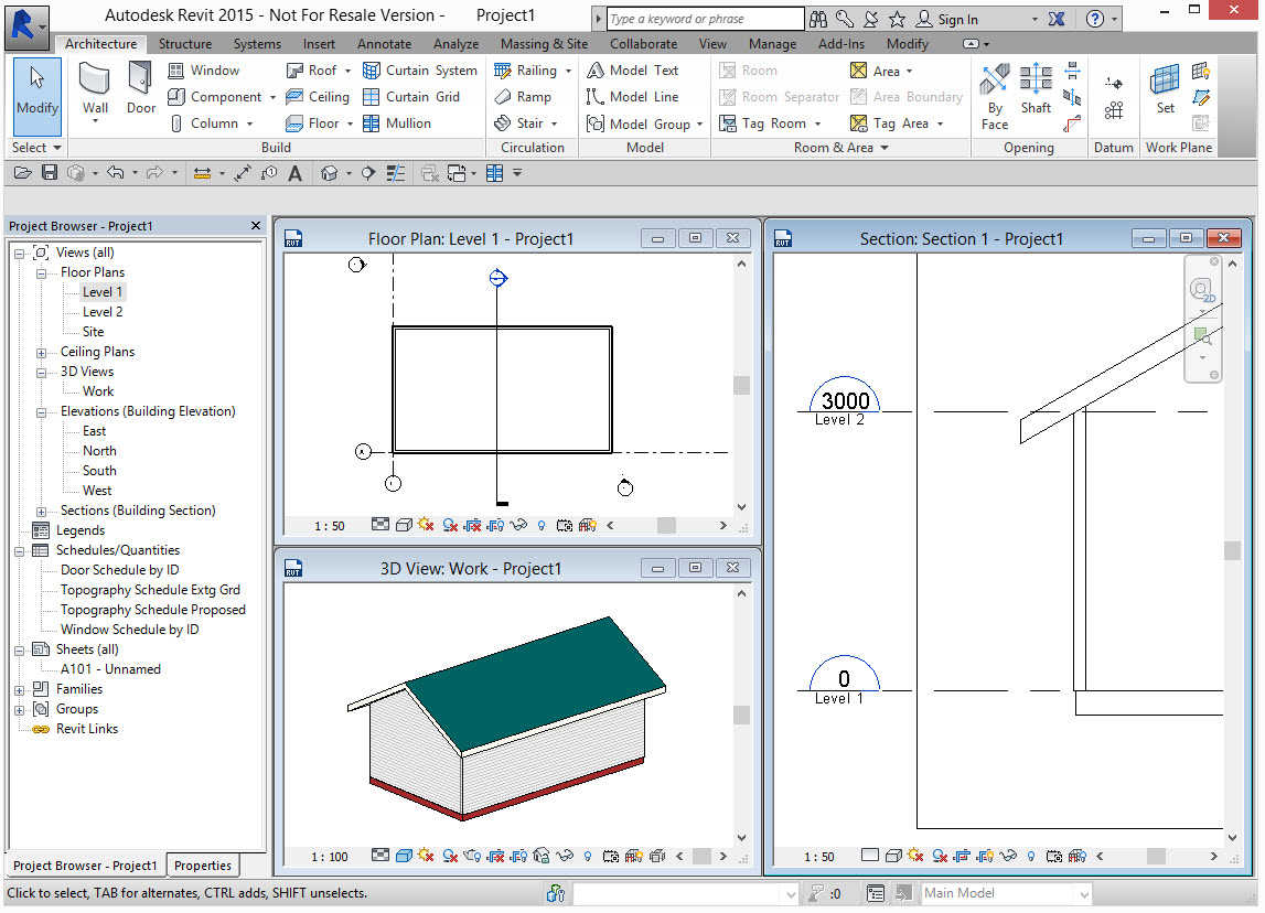
Here is my revit project. Fairly simple. It's based on the default ootb template. True North has not been set so it is the same as Project North, i.e. straight up the page. Also, the ground floor level is still at 0.
Step 2 - Link in the 3d dwg file of the site information.
This should contain:
Linework representing site contours at the correct elevation (z value) or, preferably the original triangulated network from the surveyor (ask them to include the TIN information in the dwg file).
Make sure there is some linework drawn at elevation 0 that can be used as a check datum.
Linework for the boundaries if you have it.
The Y axis of the saved coordinate system should be indicating north. Also a good idea to have some linework that indicates north. This is not strcictly neccessary but is a really good check.
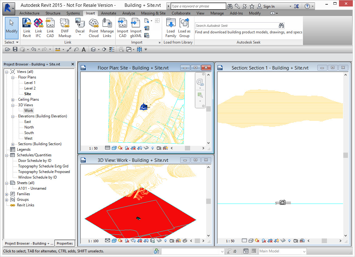
I typically link dwg files positioned Center to Center
Step 3 - Create a Topo Surface
Create a Topo Surface from the linked dwg using the Contour or TIN linework from the linked dwg.
Remember to always make the topo surface bigger than the site as it can then be trimmed back to the boundary lines using the Split Surface tool giving nice clean accurate edges to your site.
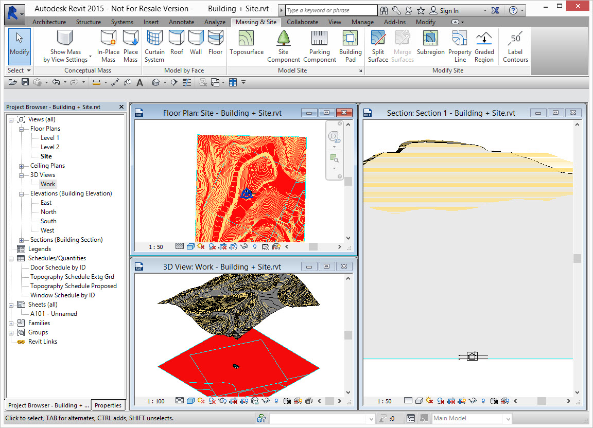
Step 4 - Move and rotate the Topo Surface & Linked dwg to be correctly positioned around your building.
We typically do not move the building elements in Revit. It is much easier to move the site around the building. Surveyors cringe when they hear this as it goes against the grain that we should move the site when they have put all that effort into correctly geo-locating the dwg file. But don't worry, it all gets sorted out in the next steps.
I have located the site in plan so the building is in the lower right corner and rotated it so the boundary is aligned with the building (you can just see the cyan bounday lines in the linked dwg).
In cross section, I have moved the site down so there is an even cut and fill.
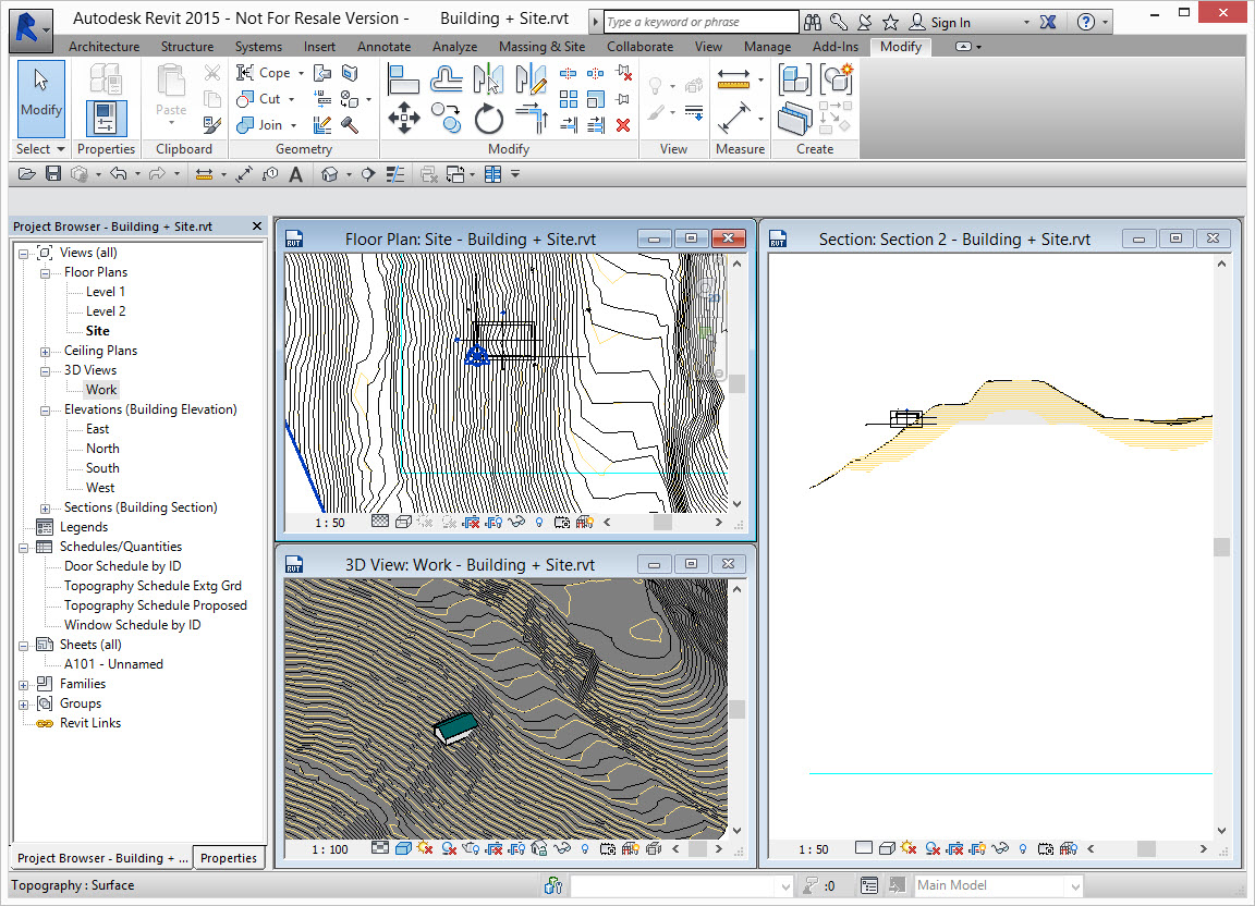
Step 5 - Geographically locate your project from information in the survey dwg
If the linked in site information dwg file was set up as listed in step 2, it can be used to geographically locate our revit project.
Before we do this we should make sure Revit's Base Point and Survey Markers are visible. It is not strictly necessary but it will help to explain what is going on in the next steps.
From Visibility/Graphics turn on Site > Base Point & Survey Marker.
The Base Point is indicated by the circle with the cross and Survey Marker is the triangle. By default they are in the same location.
Create a Shared Coordinate Site
Full Revit users can select the linked dwg. On the Properties palette, in the Shared Site field, hit the button that says <Not Shared>
Revit LT users will have to do follow a slightly different process. See Step 5a below.
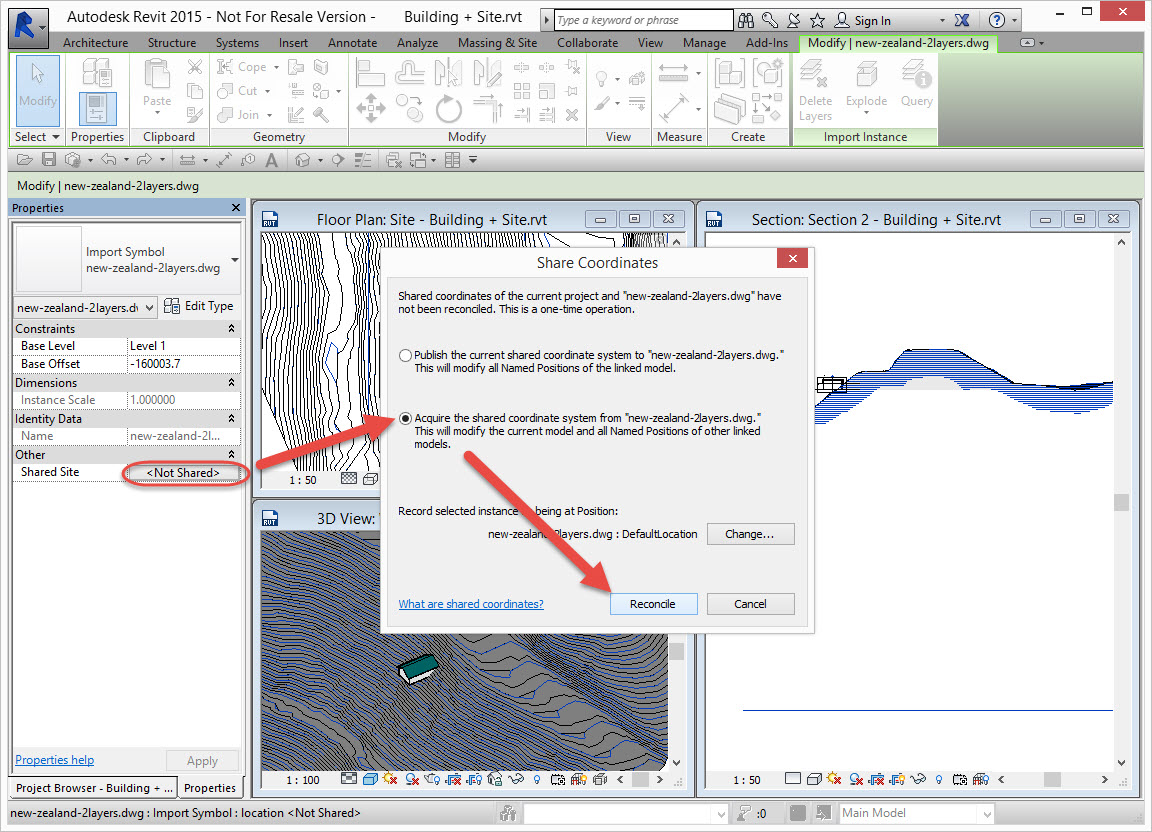
This one simple step has extracted the cordinate system from the dwg file and stored it in the revit project as a Shared Coordinate Site.
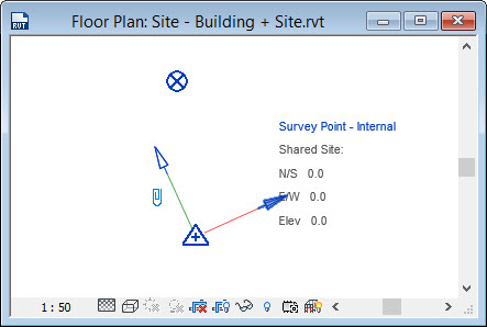
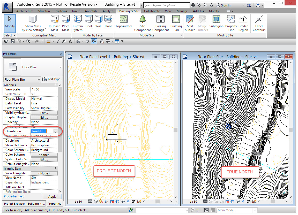
You should see that the triangle Survey Marker has moved to map onto the 0,0,0 of the linked dwg. Check this in plan and section (you may have to do a Zoom Extents and change where the section is cutting through) You can now set any plan view to be oriented as Project North or True North. The test being that when True North, the linework representing north in the linked dwg should be oriented straight up the view.
Step 5a - for Revit LT users
Revit LT doesn't have the the Shared Coordinated tools so manually move & rotate the Survey Marker to the 0,0,0 origin of the linked dwg. This can be done separately in plan and elevation.
Elevation
From an elevation or section view, use Visibility/Graphics to turn on the Site > Survey Marker
Select the triangle survey marker icon and move it down to z = 0 of the linked dwg. This is one reason for having some linework in the dwg at z = 0. You can also use the Relocate Project tool which effectively does the same thing.
Plan
In the Site Plan view or any plan view that you can see the linked dwg and more importantly, the linework representing north, set the View Orientation to True North.
Use the Rotate True North tool. Place the base of the rotation somewhere on the linework indicating north and rotate it so that it is pointing straight up the view.
Step 6 - Create Property Lines
Now you can create the Revit Property lines by tracing over the boundary linework in the linked dwg. It may help to set the view to wireframe to see all the linework in the linked dwg
Step 7 - Adjust the Level Display
The elevations and cross sections are still showing 0 as the level for the ground floor, which means they are based on the project Base Point. This can be changed to show the correct levels based on the position of the position of the Survey Marker.
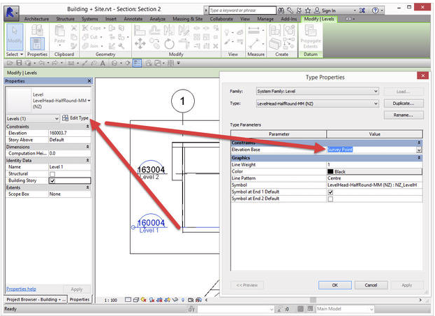
From an elevation or section view, select a level, edit the type properties and change the Elevation Base from Project Base Point to Survey Point.
Simple as that, the levels are now reporting the correct RL's.
All other annotation families that report levels and coordinates can do this as well. e.g. Spot Elevation, Spot Coordinates and Contour Labels.
